Introduction In previous posts I looked at various aspects of GMDSS/DSC using Scicos & GNU Radio (Ref.1/9). In this post I look at the underlying specification ITU M.493-16 and how the frame structure is assembled (Ref.10). The specification covers everything in great detail! It reminds me of working with X.25. I will generate a basic… Continue reading Marine GMDSS/DSC VHF Decoder_c
HF OLIVIA 64-2000 Channel on GNURadio
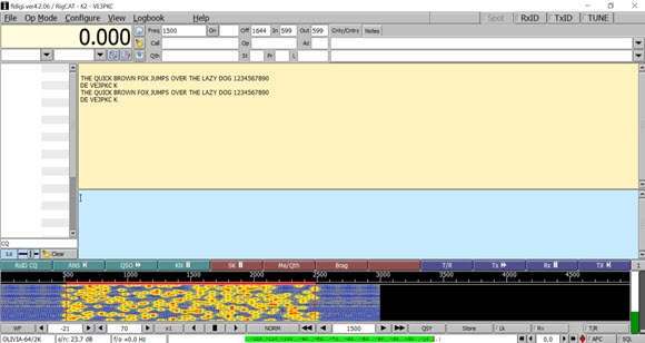
Introduction In the previous post I received an OLIVIA 64-2000 transmission as part of a ShortWave Radiogram broadcast (Ref.1). I know from my work with MFSK how robust this mode is, so I thought it would be interesting to see how the OLIVIA 64-2000 compares to MFSK64 using the same channel model I used to… Continue reading HF OLIVIA 64-2000 Channel on GNURadio
HF SDR-IQ for Olivia 64-2000

Introduction During the past several years I have received broadcasts from Short Wave Radiogram using the RTL-SDR and SDR-IQ receivers. These broadcasts featured transmissions using MFSK32/64 which I decoded with FLDIGI and Multipsk (Ref.1/3). These broadcasts illustrated the amazing noise performance of MFSK. Last week Short Wave Radiogram added a segment using OLIVIA 64-2000 (Ref.4).… Continue reading HF SDR-IQ for Olivia 64-2000
CubeSat CANVAS on GNURadio
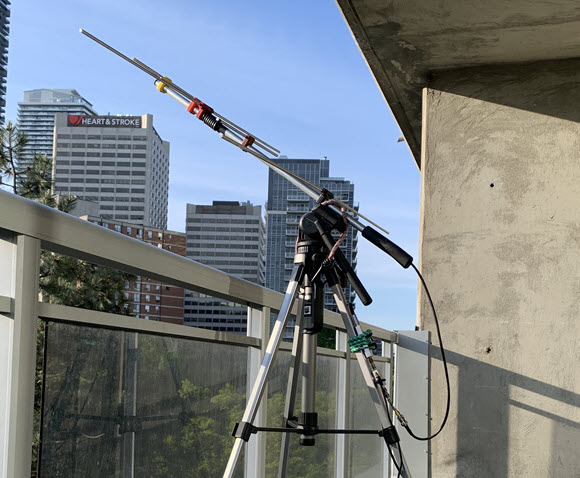
Introduction This past year I was able to successfully receive CubeSats ENSO, Veronika and EIRSAT-1 (Ref.1/3). All three CubeSats have since decayed from orbit according to the SatNOGS database. Doing a search, I found a recent CubeSat launch CANVAS (Ref.4). So I thought I would try reception using my 2m/70cm yagi. I previously used an… Continue reading CubeSat CANVAS on GNURadio
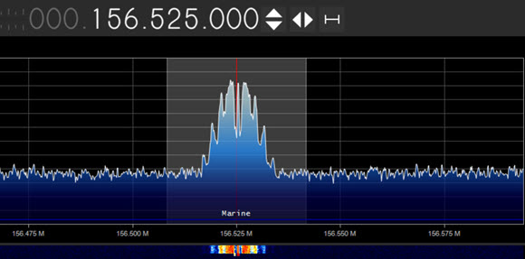
Toronto Marine Weather 162.400/162.475MHz
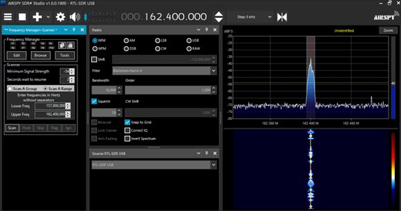
For the last six years since I have been working steadily with my YouTube channel and blog, the presence of XMJ-225 Toronto Marine Weather radio on VHF162.4MHz has been a welcome occurrence. While studying various VHF broadcasts such as AIS and DSC, I used this station as a starting placeholder. For the first generation of… Continue reading Toronto Marine Weather 162.400/162.475MHz