Introduction
In previous posts I looked at various aspects of GMDSS/DSC using Scicos & GNU Radio (Ref.1/9). In this post I look at the underlying specification ITU M.493-16 and how the frame structure is assembled (Ref.10). The specification covers everything in great detail! It reminds me of working with X.25. I will generate a basic frame and then compare this to an actual DSCVHF off-air frame decoded by both Scicos & GNURadio.
Basic Frame Construction with Dot & Phasing
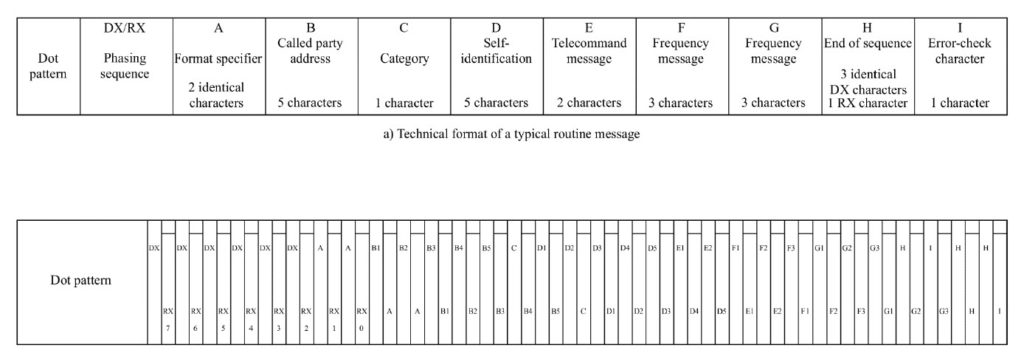
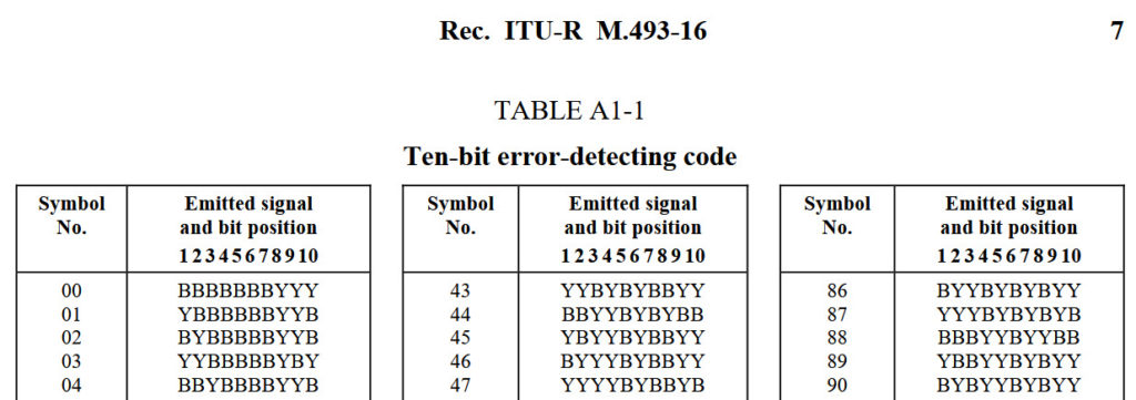
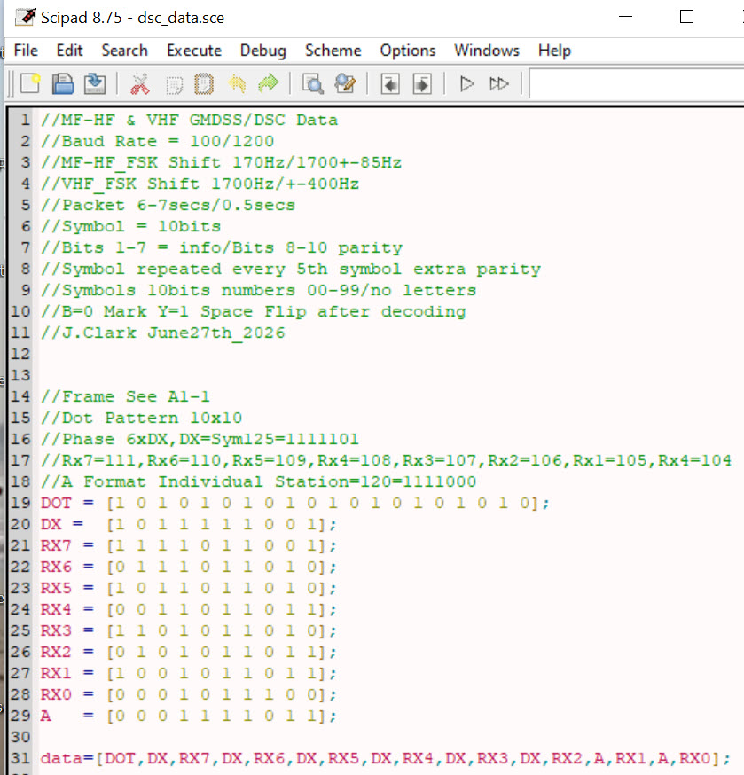
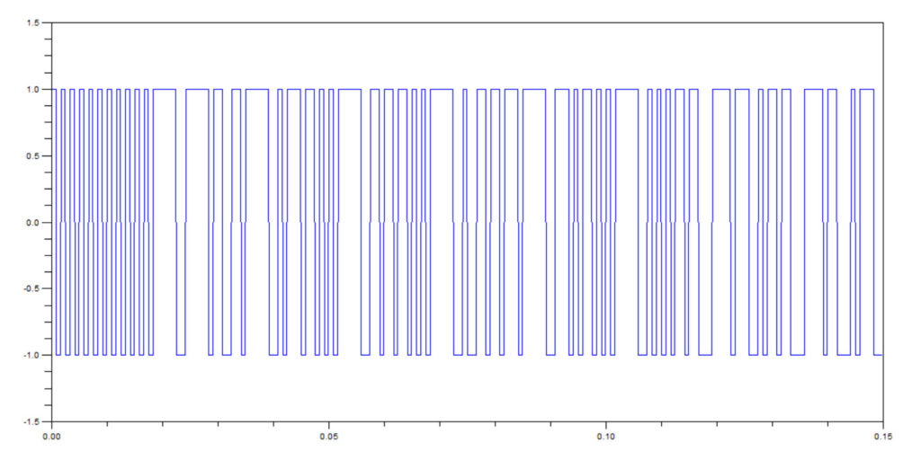
Figure 1 shows the Call Sequence Diagram A1-1 from M.493-16 (p.26). Figure 2 shows the Symbol definition table A1-1 (p.7). Figure 3 shows a simple ScicosLab encoder for the first part of the frame of dot & phasing to show the construction principle. Figure 4 shows the frame plot output.
The dot pattern consists of alternate 1’s and 0’s. This provides bit synchronization. The phasing allows for symbol synchronization. Symbols 00-127 consist of 10 bits, 7 information and 3 parity bits. Info bits are transmitted LSB first and Parity MSB first. This can be a bit tricky to understand at first. The parity bits count the number of zeros. Y stands for 1 and B stands for 0 as shown in Table A1-1.
Let’s consider an example say symbol 47 from the table.
47dec2bin=0101111 (0x64 + 1×32 + 0x16 + 1×8 + 1×4 + 1×2 + 1×1)
Now write the bits LSB first:
1111010
Count the number of zeros=2 and insert Parity MSB:
1111010:010
Replace 1 with Y and 0 with B:
YYYYBYBBYB
One final hitch. Y=1 represents a space or lower FSK frequency while B=0 represents a mark or higher frequency. This can be handled after decoding by flipping the +1/-1 to -1/+1.
Now the frame construction proceeds as follows. First the dot pattern of alternating 1/0s, then 6xDX symbols separated by 7xRX symbols and finally 2xA as shown in Figure 1. DX=125, RX7=111, RX6=110,…..RX0=104. A=120 for a call to a particular station.
DSCVHF WAV File Decoding
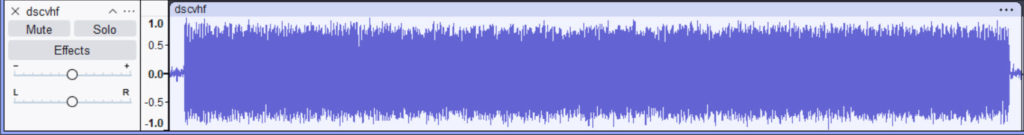
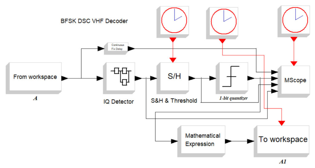
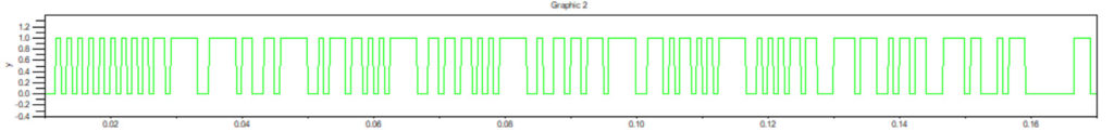
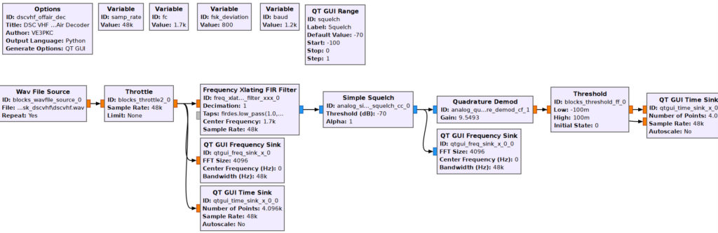
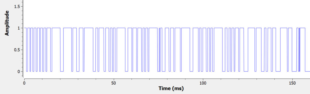
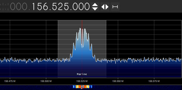
Figure 5 shows an off-air signal capture of a DSCVHF transmission to a local station saved as a WAV file. Figure 6/7 show a Scicos DSCVHF decoder and output as discussed in previous posts. Figures 8/9 show a GNURadio decoder and output. Note that all the three outputs match for the Dot/Phasing portion of the first approx 150msec.
R=1200bd, Tb=0.833msec,Tframe=0.833x18x10=150msec
HF Radio Telecommunications Learn by Simulation

Please send your comments, questions and suggestions to:
contact:

References
#1. – “Marine GMDSS/NAVTEX MF Decoder”
https://jeremyclark.ca/wp/telecom/marine-gmdss-navtex-mf-decoder/
#2. – “Marine GMDSS/DSC VHF Decoder_b”
https://jeremyclark.ca/wp/telecom/marine-gmdss-dsc-vhf-decoder_b/
#3. – “BFSK Generator on GNU Radio”
https://jeremyclark.ca/wp/telecom/bfsk-generator-on-gnuradio/
#4. – “Marine GMDSS/DSC VHF Decoder_a”
https://jeremyclark.ca/wp/telecom/marine-gmdss-dsc-vhf-decoder_a/
#5. – “RTL-SDR for HF Marine GMDSS/DSC on SDRangel”
https://jeremyclark.ca/wp/telecom/rtl-sdr-for-hf-marine-gmdss-dsc-on-sdrangel/
#6. – “VHF Marine GMDSS/DSC Decode & Scicos Simulation”
https://jeremyclark.ca/wp/telecom/vhf-marine-gmdss-dsc-decode-scicos-simulation/
#7. – “RTL-SDR for HF Marine GMDSS/DSC”
https://jeremyclark.ca/wp/telecom/rtl-sdr-for-hf-marine-gmdss-dsc/
#8. – “RTL-SDR for Marine GMDSS/DSC on RaspberryPi4”
https://jeremyclark.ca/wp/telecom/rtl-sdr-for-marine-gmdss-dsc-on-raspberrypi4/
#9. – “RTL-SDR for Marine GMDSS/DSC on Multipsk”
https://jeremyclark.ca/wp/telecom/rtl-sdr-for-marine-gmdss-dsc-on-multipsk/
#10. – “ITU Recommendation M.493-16 (12/2023)
https://www.itu.int/rec/R-REC-M.493