
Introduction
Many satellite systems such as Meteor & Inmarsat use QPSK Quadrature Phase Shift Keying type modulation. There are various types of QPSK that enhance certain properties such as OQPSK Offset QPSK. We can simulate these signals in Scicos to study their differences (Ref.1).
QPSK Scicos Simulation
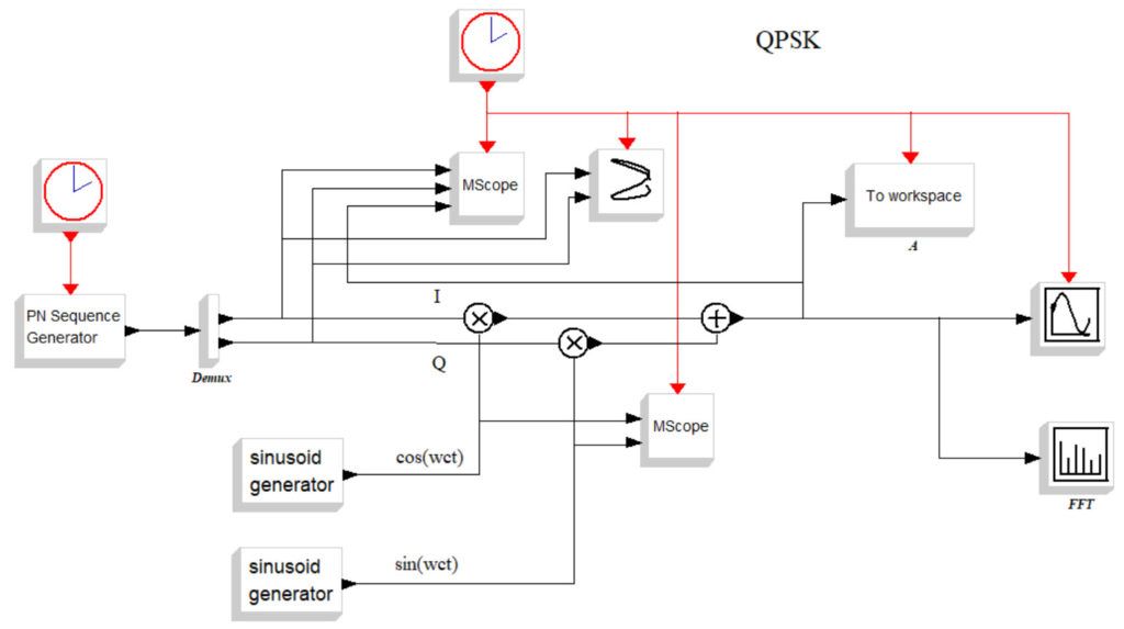
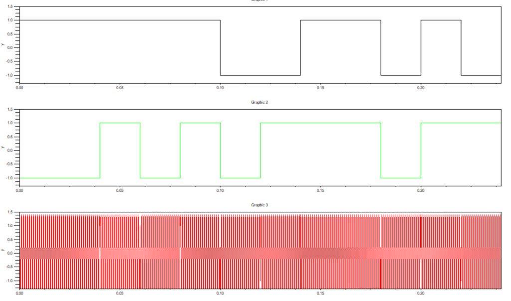
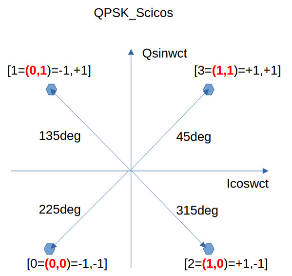
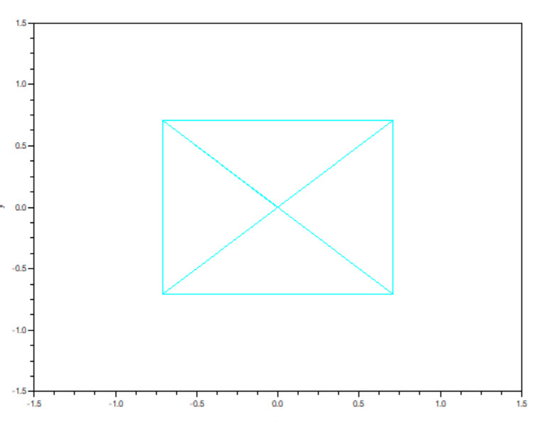
Figure 1 shows a Scicos schematic used to generate QPSK. For computational simplicity, R=100bit/sec, S=50symbols/sec (2bits per symbol) and Fc=1KHz. A PN Sequence Generator produces a stream of data at the bit rate of 100bits/sec. A demux then splits this into two random data streams of 50bits/sec at the symbol rate. Figure 2 shows the modulator waveforms. Trace 1 is the I branch data +/-1.0, Trace 2 is the Q branch data +/-1.0, and Trace 3 is the modulated QPSK output waveform. For example the first (I,Q) data is (1,-1) for 0.02sec. This corresponds to 2=(1,0)=(1,-1) at 315deg. Thus the various constellation points are filled out as shown in Figure 3. Note that phase transitions can be from either point to the nearest neighbour by +/-90deg or diagonally opposite +/-180deg. When both I & Q change from -1 to 1 or from 1 to -1 at the same time this gives rise to 180deg phase transitions as shown by notches in the output waveform.
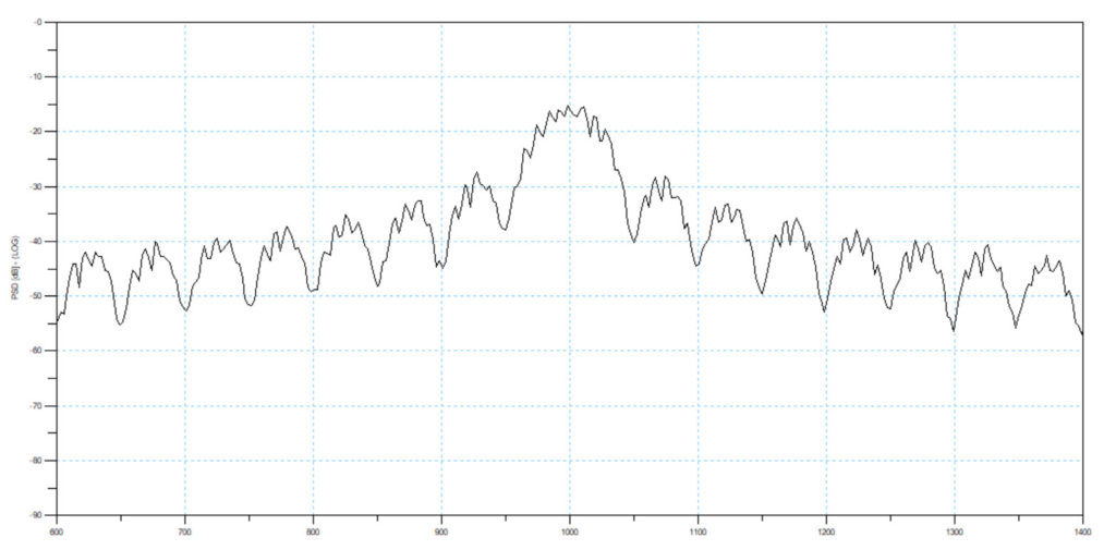
Figure 4 shows the output spectrum which for random data has a smooth sinx/x shape with nulls either side of the carrier Fc +/- 50Hz (=+/-symbol rate).
OQPSK Offset QPSK Scicos Simulation
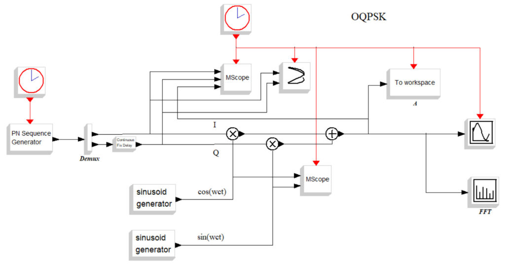
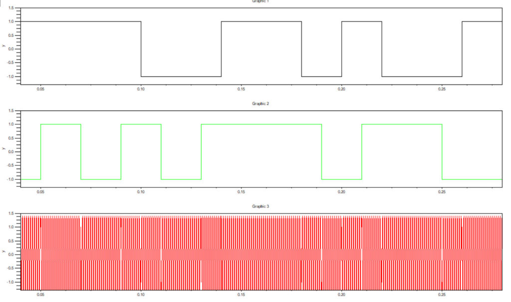
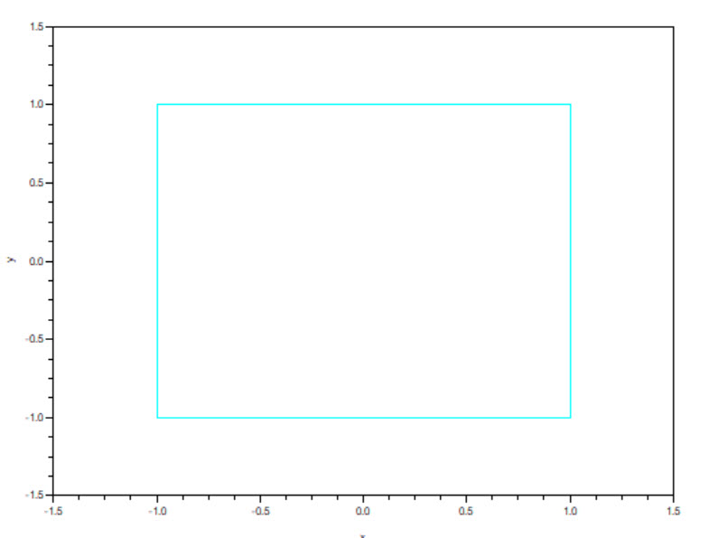
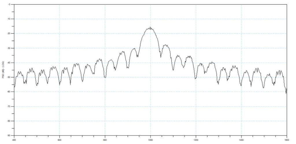
Figure 5 shows a Scicos schematic used to generate OQPSK. The schematic is identical to the QPSK one, except for a 1 bit delay inserted into the Q branch data. What this does is prevent the I & Q data from both going low or high at the same time yielding a 180deg phase shift. This improves the performance of receivers. Figure 6 shows the I & Q data as before and Figure 7 the constellations. Note there are no diagonal phase shifts now. Figure 8 gives the output spectrum which is similar.
OQPSK – LRPT Low Rate Picture Transmission
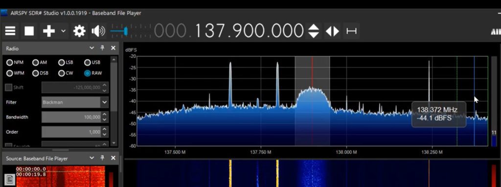
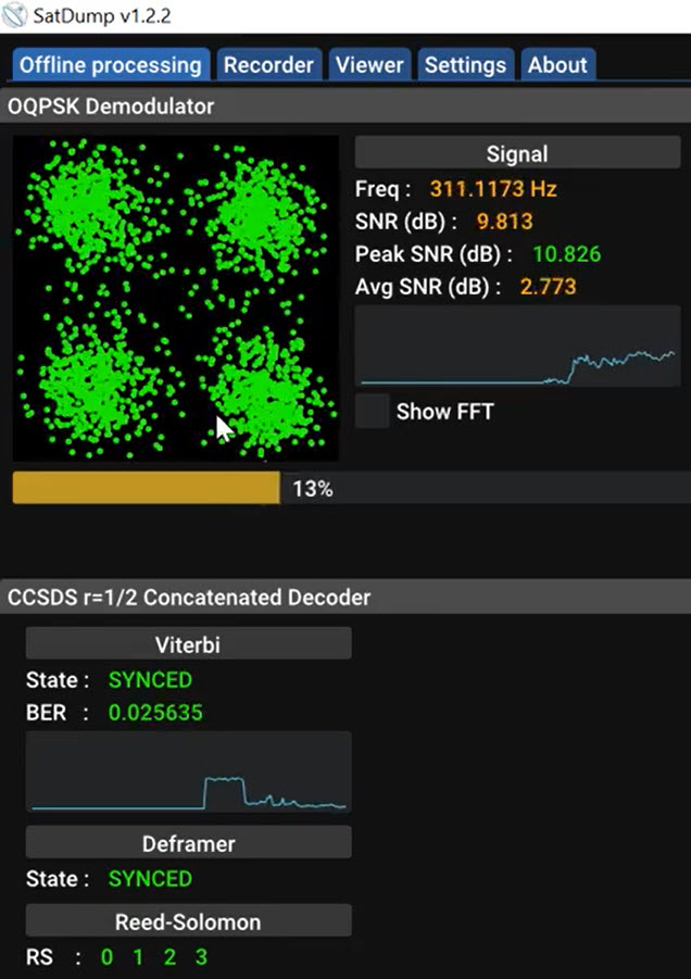
The METEOR M2-3 satellite uses LRPT Low Rate Picture Transmission Protocol to send earth weather images. Transmission is via 72Kbps OQPSK. This is shown in Figures 9/10 (Ref.2). Note the spectrum easily fits into the 100KHz SDR# window.
Learn Telecommunications by Simulation
HF Radio Telecommunications Learn by Simulation
Please send your comments, questions and suggestions to:
contact:

References
#1. – “Learn Telecommunications by Simulation”
https://www.clarktelecommunications.com/simulation.htm
#2. – “RTL-SDR for Satellite Weather – Meteor M2-3/4 “
https://jeremyclark.ca/wp/telecom/rtl-sdr-for-satellite-weather-meteor-m2-3-4/