Introduction
I first learned of Meteor Scatter communications during the late 1980s in connection with sending meteorological data from remote locations. The principle made a lot of sense, using natural occurring phenomena to aid in transmission of signals with simple and minimum equipment. Weather sensor data could be collected and sent back using a solar powered VHF transmitter. Instant communication was not required so data could be continuously resent (Ref.1). A recent article in QST magazine (Ref.2) sparked my interest in re-looking at this technology by receiving signals using WSJT-X MSK144 and the RTL-SDR (Ref.3).
Equipment Setup
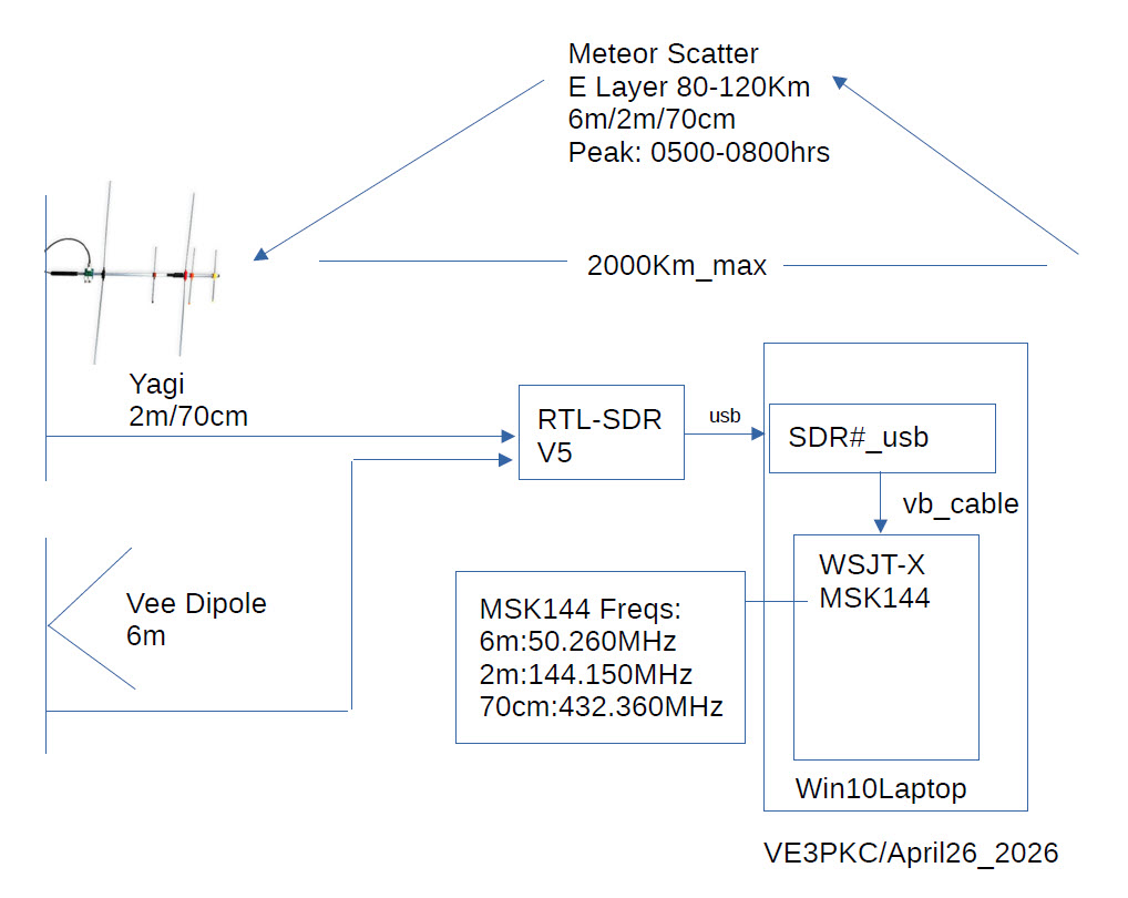
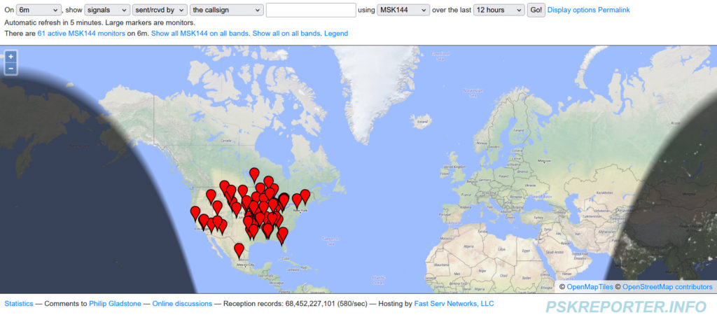
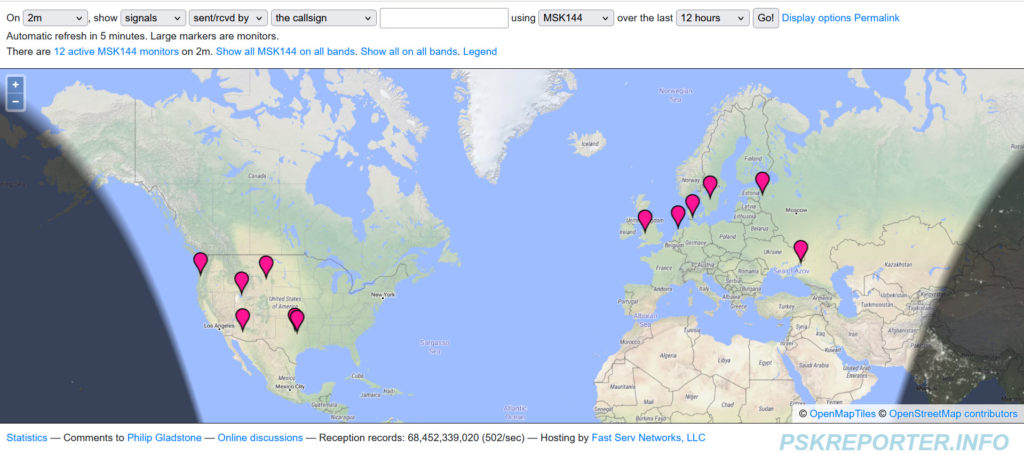
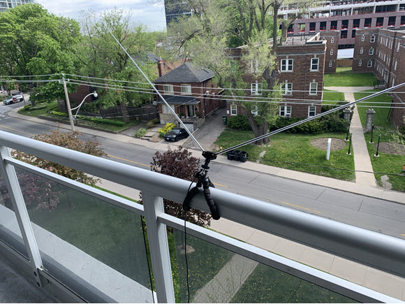
Figure 1 shows the equipment setup. Since meteor bursts last a very short time, signal information has to be compacted and sent quickly. The first systems as described in Ref.4, used CW which was sped up on transmission and slowed down on receive using magnetic tape recorders. Figures 2 & 3 show MSK144 activity on the 6m & 2m bands. Historical data indicates that the optimal frequency range for meteor scatter is 30-50MHz, so the 6m band shows far more activity.
MSK144 Parameters
Amateur operators have a long history experimenting with Meteor Scatter. First systems used high speed CW recorded on tape recorders. A big leap came in the early 2000’s with the introduction of FSK144 by K1JT. This was later improved in 2016 to the present system of MSK144.
MSK144 Key parameters are (Ref.3):
-Minimum Shift Keying, freq shift = data rate/2
-Fsp = 1000Hz, Fmrk = 2000Hz, Fc = 1500Hz, R = 2000baud,
-Transmission speed of 250cps(char/sec)
-SSB transceiver compatible bandwidth of 2500Hz
-FEC forward error correction
-SNR can be as low as -8dB
-Designed for under dense meteor “pings” less than 0.1sec
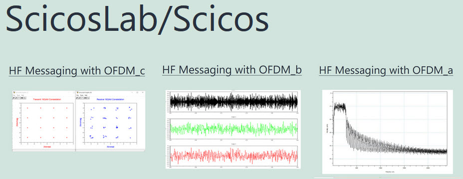
MSK144 Scicos Simulation
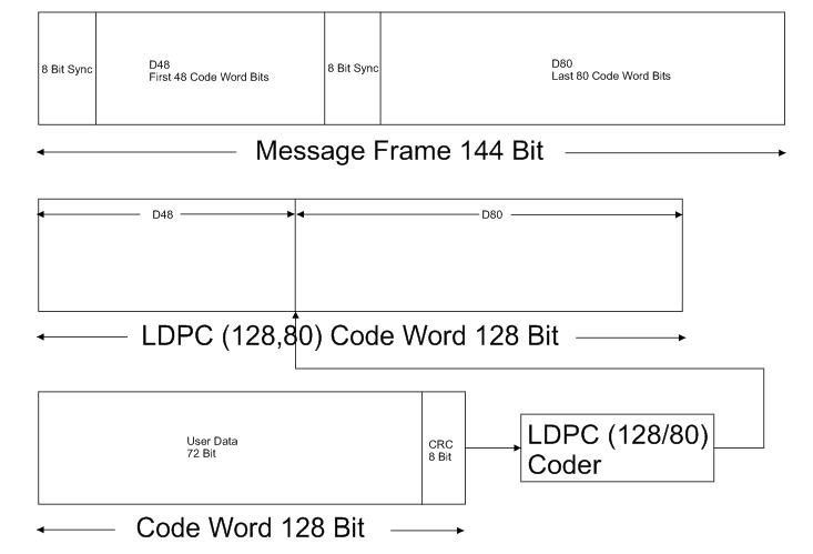
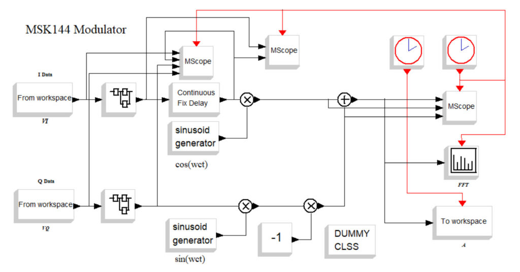
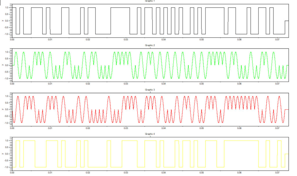
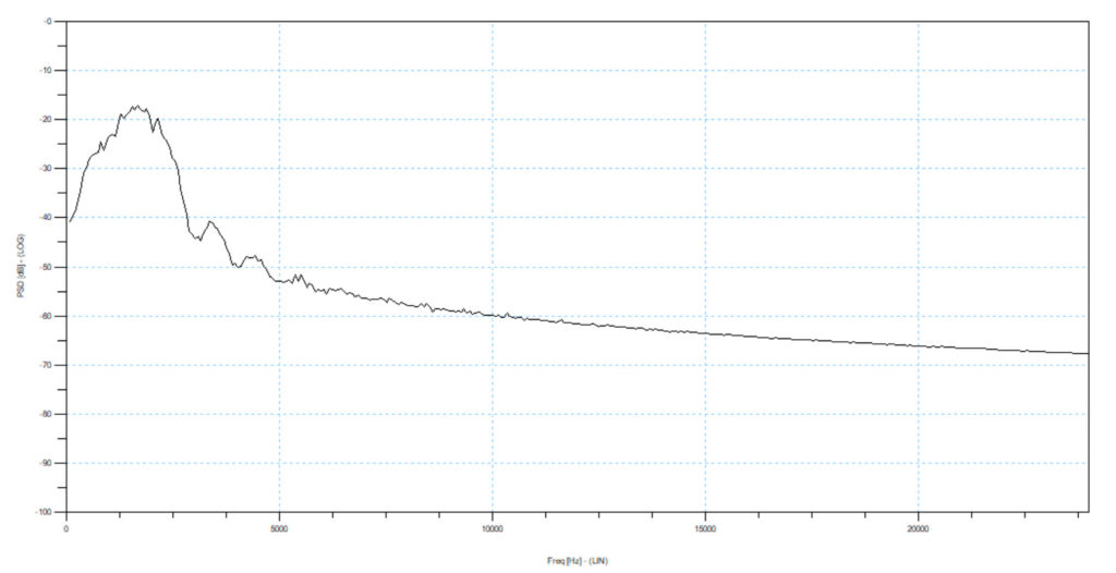
In order to get a better understanding of MSK144, we can simulate it in Scicos. Figure 4 shows the frame structure. Messages are first compressed into 72bits. An 8bit CRC and 48bits of FEC are then added (Low Density Parity Check LDPC). The 128bits are then divided into the first 48 and the last 80bits. 8bit syncs are added to form a 144bit frame. Figure 5 shows the MSK144 modulator and Figure 6 shows the I & Q data and half sine pulses. The data is chosen to match Ref.3 Figure 1. Figure 7 shows the unfiltered output spectrum.
MSK144 Reception
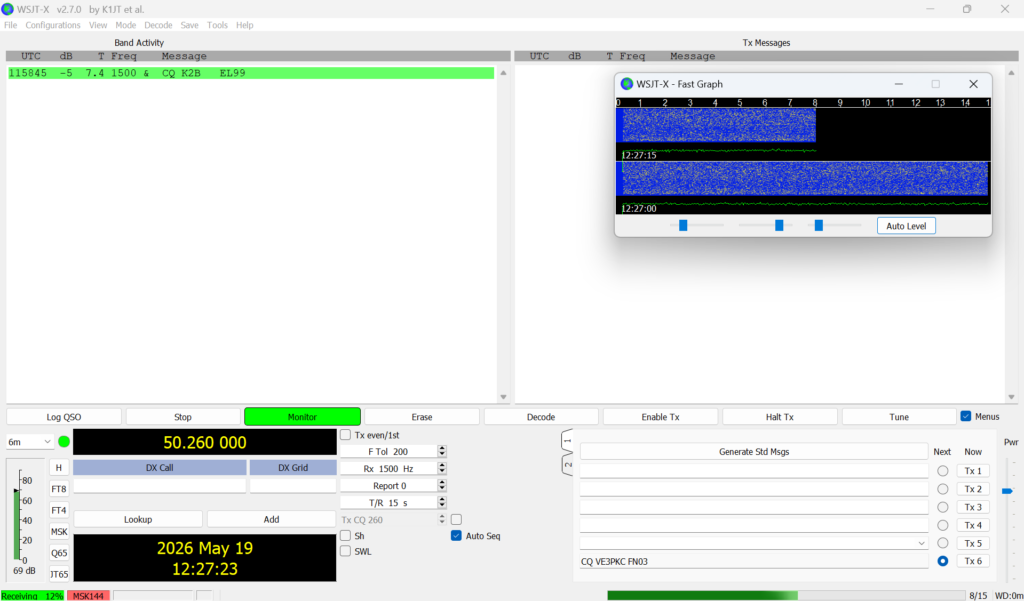
Figure 8 shows a CQ from a K2/EL99 station received at 7:58EDT. It took many tries to get a successful decode. I tried various times and locations over the past several weeks with no success. This decode was in the early morning using a Vee dipole pointing due east.
Learn Telecommunications by Simulation
HF Radio Telecommunications Learn by Simulation
Please send your comments, questions and suggestions to:
contact:

References
#1. – “Use of Meteor Scatter Telemetry for Hydrometeorological Data Collection Networks”, Risto Kalske & Ilkka Lateenhoja, Vaisala Oy
https://www.semanticscholar.org/paper/Use-of-Meteor-Scatter-telemetry-for-data-collection-Kalske-Uhteenoja/cf29886b6e5798e85b1cfde23796486c17f571a7
#2. – “Meteor Scatter: A Burst of Excitement”, ARRL QST Magazine May 2026
#3. – “The MSK144 Protocol for Meteor-Scatter Communication”, ARRL QEX Magazine September/October 2017.
#4. – “Meteor burst communications”, Wikipedia
https://en.wikipedia.org/wiki/Meteor_burst_communications
#5. – “PSKREPORTER”
https://pskreporter.info/pskmap.html