
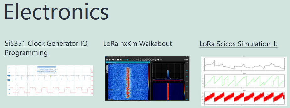
Introduction
In a recent post I looked at getting started with the Si5351A Clock Generator (Ref.1). In order to proceed quickly, I used an Adafruit module with the Si5351A and an onboard 25MHz crystal clock. The module was interfaced with an Arduino Uno and programmed with software from the Adafruit library. This produced 3 frequencies of Clk0=112.5MHz, Clk1=13.55MHz and Clk2=10.7KHz. In this post, 3 different frequencies that correspond to the 10m, 12m, & 15m WSPR bands will be programmed into Clk0, Clk1, Clk2.
Si5351A Block Diagram

Figure 1 shows the essential block diagram of the Si5351A. Note there are two separate PLLs A/B with three separate output divider circuits. The VCO operates in the 600MHz to 900MHz range. A feedback divider (m + n/d) divides this frequency down and then this is compared to the reference 25MHz oscillator. The Phase Detector produces a voltage to adjust the VCO up/down in frequency until the divided frequency is exactly equal to 25MHz. There is a further Output divider at the output of the VCO and a final integer divider R. There are various constraints on the dividers, the primary one being that integer division is preferable to fractional division to keep the jitter down. Skyworks (purchased Silicon Labs) has a Windows based program called Clockbuilder Pro (Ref.2) that calculates the various dividers based on the Clk0/1/2 frequency choices.
Si5351A ClockBuilder
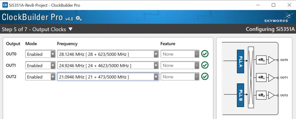
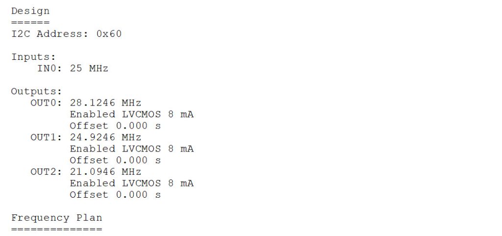

ClockBuilder Pro (Ref.2) is primarily designed to be used with an EVBU or evaluation board unit. In this case since we don’t have an EVBU, the program will detect that. You can open a new project: Create New Project/Clock Generators/Si5351A and walk through the setup. Figure 2 shows where you enter the Clk0/1/2 frequencies. Once all the data is entered, a report is produced giving you the various divider settings and register values as shown in Fig.3/4. In this case fractional feedback division is required with the VCO=899.9872MHz and (m+n/d)=35.999488 (m=35, n=1048038, d=1048575).
Si5351A Programming
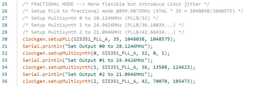
Once we have the ClockBuilder Pro report, we can setup the software. Following the earlier Adafruit software example (Ref.3) “si5351.ino”, we modify this in Arduino IDE and save as “si5351_wspr.ino”. First, remove the Integer Mode lines 25/32. Then setup the Fractional Mode for PLLA, and enter the parameters for the Feedback Divider and Output Dividers from ClockBuilder Pro as shown in Figure 5. Note that R=1 in all these cases.
Si5351A Measurement Setup
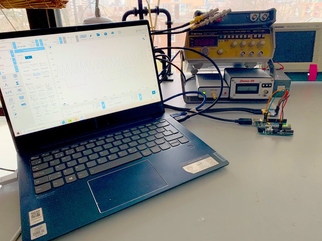
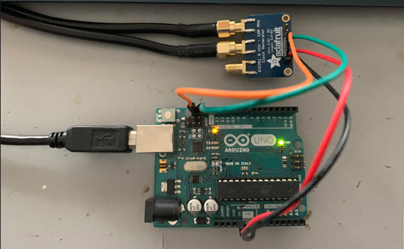
Figures 6 & 7 show the instrument setup. The Arduino, scope and spectrum analyzer are USB powered and connect to the Win 10 laptop. SMA connectors and coaxial cables have been added to the Si5351A board for good RF transmission. The scope CHA/B are terminated externally in 50ohms. The spectrum analyzer has a series 20dB pad and DC block.
Si5351A Measurements
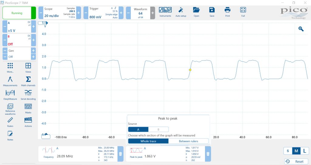
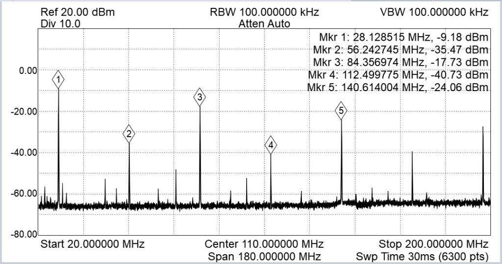
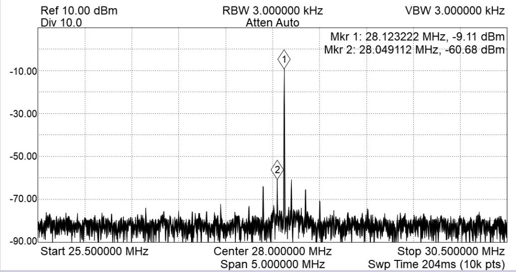
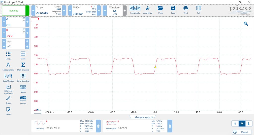
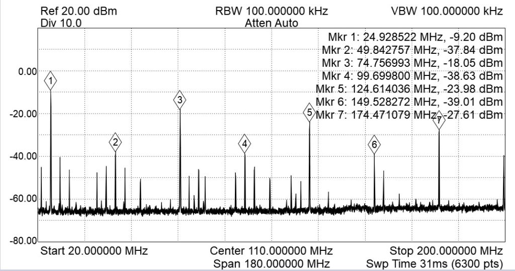
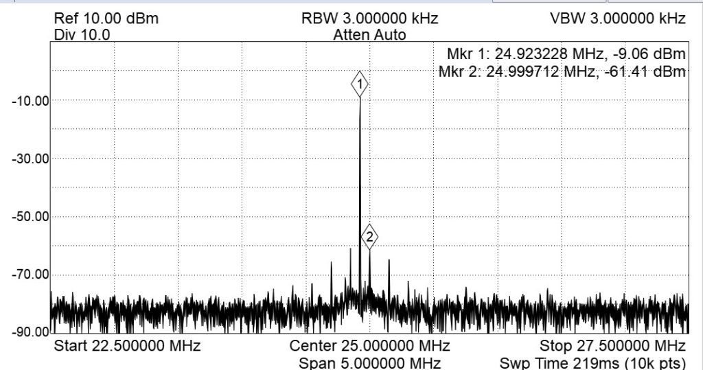
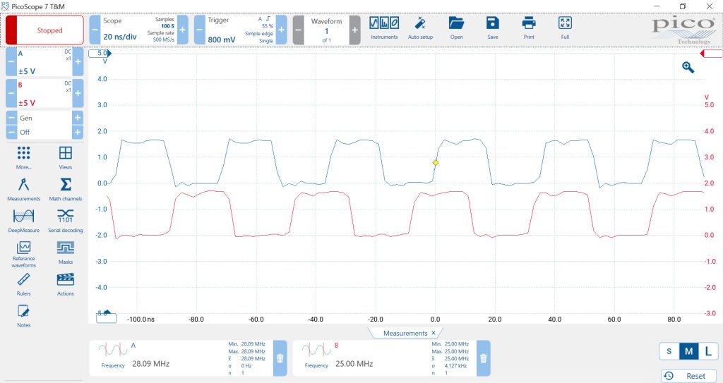
Figures 8 shows the scope view of Ch0=28.1MHz for the WSPR 10m frequency. Figures 9/10 show the wideband and narrowband spectrums for Ch0. Figure 11 shows the scope view of Ch1=24.9MHz for the WSPR 12m frequency. Figures 12/13 show the wideband and narrowband spectrums for Ch1. Figure 14 shows Ch0 & Ch1 together.
Please send your comments, questions and suggestions to:
contact:

References
#1. – “Si5351 Clock Generator Programming”
https://jeremyclark.ca/wp/telecom/si5351-clock-generator-programming/
#2. – “Skyworks ClockBuilderPro”
https://www.skyworksinc.com/en/Application-Pages/Clockbuilder-Pro-Software
#3. – “Adafruit Si5351A Coding”
https://learn.adafruit.com/adafruit-si5351-clock-generator-breakout/wiring-and-test