
Introduction

| Inmarsat Satellite (Ref.3/4)) |
| Inmarsat3-F3 (Launch 1998) Long = 27degE Elev = 35,872Km (avg) |
| Inmarsat3-F5 (Launch 1998) Long = 54degW Elev = 35,793Km (avg) Visible QTH |
| Inmarsat4-F1 (Launch 2005) Long = 143.5degE Elev = 35,794Km (avg) |
| Inmarsat4-F2 (Launch 2005) Long = 64degE Elev = 35,794Km (avg) |
| Inmarsat4-F3 (Launch 2008) Long = 98degW Elev = 35,794Km (avg) Visible QTH |
| Inmarsat4a-F4 (Launch 2013) Long = 25degE Elev = 35,794Km (avg) |
In the past several months I have been working receiving GOES16 weather signals at 1694.1MHz (Ref.1), then re-purposing the equipment to receive the radio astronomy hydrogen line at 1420.4MHz (Ref.2). Since these signals are all in the so called L band 1-2GHz, I decided I would see what else could be received in this frequency range with my existing equipment. Not to mention the fact that once you start staring into space it becomes very addictive!
The Inmarsat Satellite network has two L band satellites (3F5 & 4F3) visible from my location according to Ref.3/4. Figure 1 shows the Inmarsat L band constellation and Figure 2 lists all the L band satellites.
Dish Alignment Inmarsat3-F5 & Inmarsat4-F3
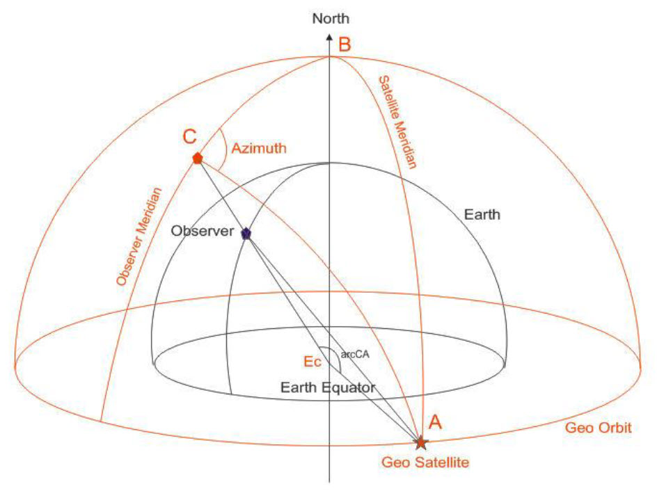


Figure 4 shows the spherical geometry drawings used to solve for the dish parameters. Figure 5 shows the Scicoslab solution for Inmarsat3-F5 and Figure 6 for Inmarsat4-F3 to my QTH. Inmarsat 3F5 is blocked at eye level, but at an elevation of 34deg just skims the top of a near by building. Inmarsat4-F3 is not visible at all, being on the other side of my building.
Equipment Configuration


Figure 7 shows the L band equipment that I have used to date for the Hydrogen Line, GPS and GOES16. I purchased an LNA/BPF & Patch Antenna for Inmarsat in case I was not able to use the L band dish (blocked path). Figure 8 shows the LNA/BPF band pass with the noise technique I have used previously.
Please send your comments, questions and suggestions to:
contact:

References
#1. – “GOES16 Weather Satellite – Signal Capture with Dish Balcony Mount”
https://jeremyclark.ca/wp/telecom/goes16-weather-satellite-signal-capture-with-dish-balcony-mount/
#2. – “RTL-SDR for Radio Astronomy – Signal Capture2”
https://jeremyclark.ca/wp/telecom/rtl-sdr-for-radio-astronomy-signal-capture2/
#3. – “Inmarsat”, Wikipedia
https://en.wikipedia.org/wiki/Inmarsat
#4. – “N2YO Satellite Tracking”
https://www.n2yo.com/