Introduction
In previous posts I examined the possible use of OFDM for HF messaging (Ref.1/2/3) and for voice (Ref.4). I introduced several channel models using Scicos: an 8 channel discrete model and a 64 channel model using IFFT/FFT. In this post I will focus on using FEC Forward Error Correction to improve the transmission performance.
HF Error Detection & Correction

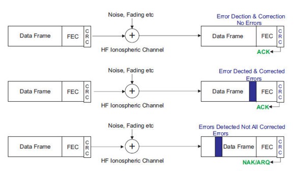
HF modems may or may not contain error detection and correction. PSK31 for example is essentially keyboard to keyboard transmission with no error detection or correction. Figure 1 illustrates the concepts. If the modem is sending critical data such as emails etc, then the overall transmission has to be error free. CRC codes are used to detect whether errors have occurred. If a data frame is sent and received correctly, then an ACK is sent back to the transmitter to indicate the frame was received correctly and the next frame can be sent. If an error(s) occurred and the FEC was able to correct it, then an ACK is also sent back. However, if errors occurred and were not able to be corrected, then a NAK is returned to the transmitter to indicate to resend the data frame.
Error Detection


Figure 2 shows a simple static Simulink model with a CRC-4 code used to detect errors on a simple 2byte=16bit data frame. No errors are made so the detector syndrome is “0”. Figure 3 shows transmission errors on the first and last bit. The detector syndrome indicates “1” for error(s) detected. Normally CRC-16/32 is used in communications.
FEC Forward Error Correction


Figure 4 shows a static Simulink model of a BCH (15,5) code (Ref.5). This a particular case of a so called (n,k) block codes with a total of n bits, k information bits and n-k parity bits. The parity bits are chosen in such a way as to correct particular transmission errors. In this case there are errors in the 1st, 2nd and last bits, these are corrected. In Figure 5 there are four errors and these cannot be corrected as this is beyond the error correcting ability of the code. Note that adding parity bits increases the data load from 5bits to 15 in this case. Each application has to be analyzed for overall data throughput on a real channel vs NAK/ARQ transmissions etc. This is where simulation can play an important role to model the different types of channels anticipated.
BER Bit Error Rate Measurement


Figure 6 shows a data signal being passed through a baseband channel where AWGN Additive White Gaussian Noise is added. A BER Bit Error measurement is made comparing the sampled signal+noise with the original signal. If the sample > 0.5V, then a 1 is declared. If the sample <= 0.5 then a 0 is declared (signal amplitude 0V-1V). This is compared against the original signal and if different, an error is declared. Figure 7 shows theoretical BER vs. SNR curves for BPSK (Ref.6/7).
BER Measurement on GNU Radio


| noise_stdev | BER | SNR=10log((E/stdev)^2) db | Theory dB |
| 0.225 | 10^-6 | 13 | 10.5 |
| 0.275 | 10^-5 | 11 | 9.5 |
| 0.350 | 10^-4 | 9 | 8.5 |
| 0.475 | 10^-3 | 6.5 | 7 |
| 0.800 | 10^-2 | 2 | 4 |
Figure 8 shows a GNU Radio schematic used to evaluate BPSK baseband BER (Ref.8) The Random Source produces 0’s and 1’s. The Map block maps the 0’s to -1’s and 1’s to 1’s creating a bipolar BPSK signal. Gaussian noise is added with the Fast Noise Source. The Bit Slicer samples at the sample time and creates a 1 if >0V and 0 if <=0V. This drives the BER block. To measure <10^-6, the QT Number sink time has to be adjusted >1sec. Figure 9 shows the noise_stdev slider, noise amplitude and signal+noise amplitude and BER result. Figure 10 shows a table of results that are close to theoretical values.
BER Measurement with FEC on GNU Radio


Working with FEC on GNU Radio is much more complicated than static models on Simulink or Octave. This is because it can be used with real hardware, streaming actual data. This is well described in Ref.8. Figure 11 is an example taken from gr-fec for a polar coder (../GNURadio-3.8/share/gnuradio/examples/fec/polar_code_example.grc). Figure 12 shows the response with the uncoded data receiving transmission errors at BER=10^-4, whereas coded data has no errors. Note there exists a hierarchy of blocks in order to simplify and abstract the coding:
Polar Code Configurator
Polar Encoder Definition
FEC Extended Encoder
Polar Decoder SC Definition
FEC Extended Decoder

Please send your comments, questions and suggestions to:
contact:

References
#1. – “HF Messaging with OFDM_c”
https://jeremyclark.ca/wp/telecom/hf-messaging-with-ofdm_c/
#2. – “HF Messaging with OFDM_b”
https://jeremyclark.ca/wp/telecom/hf-messaging-with-ofdm_b/
#3. – “HF Messaging with OFDM_a”
https://jeremyclark.ca/wp/telecom/hf-messaging-with-ofdm_a/
#4. – “OFDM for SSB_USB”
https://jeremyclark.ca/wp/telecom/ofdm-for-ssb_usb/
#5. – “An Introduction to Error-Correcting Codes”, Shu Lin, Prentice-Hall, 1970, LCC 76-124417
#6. – “BER”,
https://en.wikipedia.org/wiki/Bit_error_rate
#7. – “BPSK BER”,
http://www.dsplog.com/2007/08/05/bit-error-probability-for-bpsk-modulation/
#8. – “Protect Your Bits: Introduction to gr-fec A look into the error-correction capabilities of GNU Radio”, Martin Braun
https://www.youtube.com/watch?v=uVsklzjQRUU